
Multichannel Ultrasonic flaw Detector AUGUR-ART
(Equipment / Material)
Model Number: АРТ
Condition: New
Location or Storage Country: Russia
Service Engineering Support: Yes
Warranty: No
Price: Call for price
Description:
Multichannel ultrasonic flaw detector using phased arrays and digital antenna focusing technologies.
Overview:
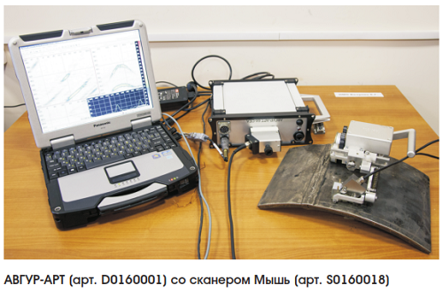
The AVGUR-ART R flaw detector in a portable design is supplied as a monoblock, including multi-channel electronics in a configuration from 32x32 to 64x128PR with additional support for up to 2 pairs of TOFD channels.
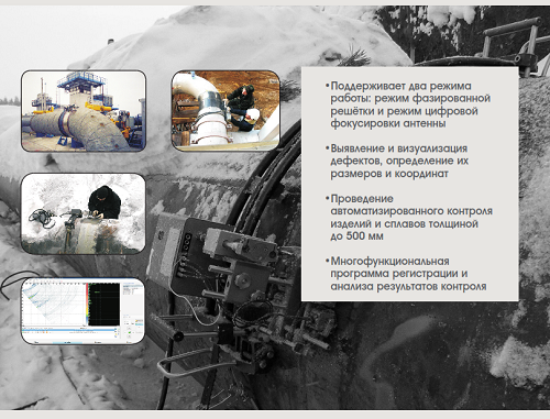
The ultrasonic multichannel flaw detector with digital focusing and automated scanning by antenna arrays AUGUR-ART is designed for:
- identification and visualization of discontinuities, determination of their sizes and coordinates, amplitudes of echo signals.
- conducting automated ultrasonic testing (AUZK) of welded joints and the base metal of equipment, parts, pipelines and other metal products, their alloys and other materials, including objects made of pearlitic and austenitic steels with a thickness of 6 to 500 mm.
Inspection using the AVGUR-ART flaw detector can be carried out at facilities located both in the process of construction (manufacturing, construction, installation), and during operation.
The operating principle of the flaw detector is based on the acoustic echo method of non-destructive testing using antenna arrays (AR). The flaw detector operates in the digital antenna focusing (DFA) mode, which has a number of advantages compared to the phased array (FR) mode.
The flaw detector supports data collection over 64 channels in the DSC mode. The flaw detector implements the TOFD operating mode.
DSC mode is a technology of obtaining acoustic images with continuous focusing at all points of the image. In the CFA mode, at the first stage, data collection is performed when enumerating all the emitter-receiver combinations for a linear AR, and at the second stage, mathematical processing of the obtained data is performed using the Raman SAFT (C-SAFT) algorithm. When using DSC, the same and high resolution is provided throughout the image; a coherent image is formed in only one layer. Alternative names of the CFA mode in foreign sources are Full Matrix Capture (FMC) or Sampling Phased Array.
To ensure high resolution and increase the signal-to-noise ratio when controlling thick-walled objects, two versions of DFAs with synthesizing apertures are used due to the precision mechanical movement of the AR along and across the axis of the welded joint; then, joint mathematical processing of the received echo signals is performed using the algorithms CFA-X, CFA-Y, CFA-XY.
SOFTWARE FOR DEFECTOSCOPE AUGUR-ART
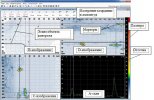
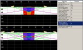
The flaw detector AVGUR-ART is equipped with software (software) that controls the flaw detector operation, collection, systematic long-term storage and processing of data using the C-SAFT algorithm and other methods. The flaw detector software package includes the “AUGUR-ART Registration” program, designed to configure control parameters, visualize discontinuity images, collect control data, the “AUGUR-ART” verification program, designed to check the parameters of a flaw detector’s transceiver path used by the AR and the “ Data Analysis ”, intended for processing and visualization of AUZK data.
AVGUR-ART software is installed on the control computer and at the workplace for data processing and archiving.
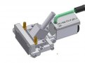
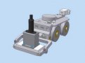
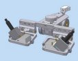
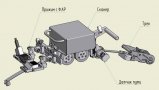
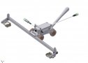
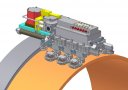
Scanning devices are used with the AVGUR-ART flaw detector, which allow you to move the antenna arrays manually or in an automated mode along one or two coordinate axes.
The choice of the type of scanning device is determined by the parameters of the control object.
Scanning devices can be understaffed with a battery scanner control unit and clamps for working with flaw detectors from other manufacturers. For special control tasks, specialized SCs can be developed.
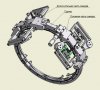
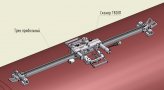
SCANNING DEVICES FOR DEFECTOSCOPE AUGUR-ART

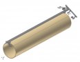
Training samples
To calibrate the RF installed on the prism, a tuning sample is used:
Tuning sample T-B-18-0-St20 (art. TB0180033) |
To carry out sensitivity settings, system visualization parameters, tuning samples are used in accordance with the requirements of the control methodology.
APPLICATION PERMISSIONS
Flaw detector fully complies with the requirements of standards and specifications
oISO 18563-1: 2015 NON-DESTRUCTIVE TESTING - CHARACTERIZATION AND VERIFICATION OF ULTRASONIC PHASED ARRAY EQUIPMENT - PART 1: INSTRUMENTS
oРР Gazprom 2-4.3-1166–2018 Welding and non-destructive testing. Equipment and materials for preparation, assembly and heating during welding and installation works. General specifications
o GOST R 05/05/13-2019 Conformity assessment system in the field of atomic energy use. Ultrasonic inspection of welded joints using phased array technology. Order of conduct
Using a flaw detector, work is carried out according to the following methods
840.44 M Method of ultrasonic testing of welded joints of Du300 pipelines using phased array technology (RBMK)
MFAR.AE12.T2M / 2-K-11 Methods of ultrasonic testing of composite welded joints for welding equalization piping, welding of injection nozzles for pressure compensators and welding of nozzles SAOZ of the VVER-440 reactor vessel to the adapter sleeve using phased array technology
MFAR.AE12.T2M / 2-K-11 Technique for automated ultrasonic testing of ring austenitic welded joints of injection pipelines and pressure relief pipelines of VVER-1000 reactors using antenna arrays
The methodology establishes the procedure for conducting non-destructive ultrasonic testing of the metal state of annular austenitic welded joints of injection pipelines and compensator discharge pipelines using antenna arrays. It provides identification, determination of conditional dimensions and the position of discontinuities in the welded joint that arise during operation, during installation and repair.
MFAR.AE12.T0S / 4-K-11 Technique for automated ultrasonic testing of heterogeneous (composite) welded joints of breathing pipelines 426x40 pressure compensator for VVER-1000 reactors using phased array technology
The methodology establishes the procedure for conducting non-destructive ultrasonic testing of the metal state of dissimilar annular welded joints of breathing pipelines 426x40 of the pressure compensator of VVER-1000 reactors using phased array technology. It provides identification, determination of conditional dimensions and the position of discontinuities in the welded joint that arise during operation, during installation and repair.
MFAR.AE12.P0S / 9-K-11 Technique for automated ultrasonic testing of heterogeneous (composite) welded joints of steam discharge and injection pipes with pressure compensator pipes of VVER-1000 reactors using antenna arrays
The methodology establishes the procedure for automated ultrasonic testing of heterogeneous welded joints of steam discharge and injection pipes with pressure compensator pipes of VVER-1000 reactors using antenna arrays. It provides identification, determination of conditional dimensions and the position of discontinuities in the welded joint that arise during operation, during installation and repair. The control zone includes deposited weld metal (including the root of the weld, the fusion line and the base metal adjacent to the area. Longitudinally oriented discontinuities are detected; sizes of discontinuities (height and length along the weld joint) can be determined.
MPA.AE.4.M0B.0.BL-12 Method of ultrasonic testing of rectilinear and curvilinear joints of ISU of 316L / ХМ19 steels for the ITER DO diverter using antenna arrays
MFAR.AE12.P1B / 8-K-12 Methods of ultrasonic testing of welded joints for welding of heat carrier collectors to the body of the PGV-1000 steam generator using phased array antenna technology
The methodology establishes the procedure for automated ultrasonic testing of the collector welding assembly to the body of the PGV-1000 steam generator of the VVER-1000 reactor using ultrasonic antenna arrays. It provides identification and sizing of technological and operational discontinuities of longitudinal, transverse, diagonal orientation
MFAR.AE2.T2M / 2-K-13 Method of ultrasonic testing of welded joints of austenitic pipelines Du300 using phased array technology
The methodology establishes the procedure for conducting non-destructive ultrasonic testing of the state of metal of ring welded joints (SS) of austenitic pipelines and collectors of Du300 KMPT reactor type RBMK-1000 using phased array antenna technology. It provides identification, location and measurement of dimensions - the length and height of longitudinal discontinuities in the SS, arising both during its installation or repair, and during operation.
MFAR.AE11.POM / 26-K-11 Methods of ultrasonic testing of composite welded joints for welding equalization piping, welding of injection nozzles for pressure compensators and welding of nozzles SAOZ of the VVER-440 reactor vessel to the adapter sleeve using phased array technology
The methodology establishes the procedure for conducting non-destructive ultrasonic testing of composite welded joints for welding equalizer piping, welding of injection nozzles of pressure compensators VVER-440 V-230 and welding of nozzles of SAOZ of the reactor vessel VVER-440 V-219 to the adapter sleeve using phased array technology. It is designed to identify discontinuities, determine their reflectivity, conditional dimensions and location in the welded joint, arising during operation, during installation and repair and having a longitudinal and transverse orientation relative to the axis of the welded joint.
Methodology for ITER Methods of ultrasonic testing of rectilinear and curvilinear joints of ISU of 316L / XM19 steels for DO ITER using antenna arrays.
The methodology establishes the procedure for non-destructive ultrasonic testing of rectilinear and curvilinear joints of ISU of 316L / ХМ19 steels for the ITER DO diverter using antenna arrays. It is designed to detect discontinuities, determine their size and location in the control object, which is a bimetallic sample (316L / ХМ19) with a GUI connection and a component of the steel support DO of the ITER divertor. A control is performed of a region with a width of ± 5 mm adjacent to the interface between the parts to be welded. This ensures the detection of discontinuities in the control zone with a reflectance corresponding to a flat-bottomed reflector with a diameter of 2 mm.
GOST R 50.05.13-2019 Ultrasonic testing of welded joints using phased array technology. Order of conduct
MFAR-TD-NX1-120 Automated ultrasonic testing of welded joints with wall thickness from 8 to 120 mm using flaw detector with phased arrays. Control Instructions
MFAR-NX1-T2M / 12-L-17 Automated ultrasonic testing of austenitic welded joints with wall thicknesses from 5 to 20 mm using flaw detectors with phased arrays. Control Instructions
MT 1.2.1.15.001.1085-2015. MT 1.2.1.15.001.1086-2015. MT 1.2.1.15.001.1087-2015 Continuous ultrasonic thickness measurement of equipment and piping of power units of nuclear power plants. Collection of methods of SUST.
MT 1.2.1.15.001.0990-2014 Automated ultrasonic testing of phased arrays of dissimilar and austenitic ring welded joints of pipelines with wall thicknesses from 5 to 20 mm and diameters of more than 108 mm of power units of VVER-1000 NPP
MT 1.2.1.15.001.1001-2016 Automated ultrasonic inspection of ring welded joints of shells of steam generators using an automated control system with a full automation cycle
MT 1.2.1.15.001.0989-2014 Automated ultrasonic testing of the weld-on assembly of the heat-collector to the nozzle Du1200 of the PGV-1000 steam generators using phased array technology. Methodology
OOO "NPC" EHO + "
Main Products/Services: Development and production of modern ultrasonic non-destructive testing systems
Registration: Russia Moscow
Year Established: 1990